System, AHB and APB busses clocks configuration functions.
More...
System, AHB and APB busses clocks configuration functions.
 ===============================================================================
      ##### System, AHB and APB busses clocks configuration functions #####
 ===============================================================================
    [..]
      This section provide functions allowing to configure the System, AHB, APB1 and
      APB2 busses clocks.

      (#) Several clock sources can be used to drive the System clock (SYSCLK): HSI,
          HSE and PLL.
          The AHB clock (HCLK) is derived from System clock through configurable
          prescaler and used to clock the CPU, memory and peripherals mapped
          on AHB bus (DMA, GPIO...). APB1 (PCLK1) and APB2 (PCLK2) clocks are derived
          from AHB clock through configurable prescalers and used to clock
          the peripherals mapped on these busses. You can use
          "RCC_GetClocksFreq()" function to retrieve the frequencies of these clocks.

      -@- All the peripheral clocks are derived from the System clock (SYSCLK) except:
        (+@) I2S: the I2S clock can be derived either from a specific PLL (PLLI2S) or
             from an external clock mapped on the I2S_CKIN pin.
             You have to use RCC_I2SCLKConfig() function to configure this clock.
        (+@) RTC: the RTC clock can be derived either from the LSI, LSE or HSE clock
             divided by 2 to 31. You have to use RCC_RTCCLKConfig() and RCC_RTCCLKCmd()
             functions to configure this clock.
        (+@) USB OTG FS, SDIO and RTC: USB OTG FS require a frequency equal to 48 MHz
             to work correctly, while the SDIO require a frequency equal or lower than
             to 48. This clock is derived of the main PLL through PLLQ divider.
        (+@) IWDG clock which is always the LSI clock.

      (#) For STM32F405xx/407xx and STM32F415xx/417xx devices, the maximum frequency
         of the SYSCLK and HCLK is 168 MHz, PCLK2 84 MHz and PCLK1 42 MHz. Depending
         on the device voltage range, the maximum frequency should be adapted accordingly:
 +-------------------------------------------------------------------------------------+
 | Latency       |                HCLK clock frequency (MHz)                           |
 |               |---------------------------------------------------------------------|
 |               | voltage range  | voltage range  | voltage range   | voltage range   |
 |               | 2.7 V - 3.6 V  | 2.4 V - 2.7 V  | 2.1 V - 2.4 V   | 1.8 V - 2.1 V   |
 |---------------|----------------|----------------|-----------------|-----------------|
 |0WS(1CPU cycle)|0 < HCLK <= 30  |0 < HCLK <= 24  |0 < HCLK <= 22   |0 < HCLK <= 20   |
 |---------------|----------------|----------------|-----------------|-----------------|
 |1WS(2CPU cycle)|30 < HCLK <= 60 |24 < HCLK <= 48 |22 < HCLK <= 44  |20 < HCLK <= 40  |
 |---------------|----------------|----------------|-----------------|-----------------|
 |2WS(3CPU cycle)|60 < HCLK <= 90 |48 < HCLK <= 72 |44 < HCLK <= 66  |40 < HCLK <= 60  |
 |---------------|----------------|----------------|-----------------|-----------------|
 |3WS(4CPU cycle)|90 < HCLK <= 120|72 < HCLK <= 96 |66 < HCLK <= 88  |60 < HCLK <= 80  |
 |---------------|----------------|----------------|-----------------|-----------------|
 |4WS(5CPU cycle)|120< HCLK <= 150|96 < HCLK <= 120|88 < HCLK <= 110 |80 < HCLK <= 100 |
 |---------------|----------------|----------------|-----------------|-----------------|
 |5WS(6CPU cycle)|150< HCLK <= 168|120< HCLK <= 144|110 < HCLK <= 132|100 < HCLK <= 120|
 |---------------|----------------|----------------|-----------------|-----------------|
 |6WS(7CPU cycle)|      NA        |144< HCLK <= 168|132 < HCLK <= 154|120 < HCLK <= 140|
 |---------------|----------------|----------------|-----------------|-----------------|
 |7WS(8CPU cycle)|      NA        |      NA        |154 < HCLK <= 168|140 < HCLK <= 160|
 +---------------|----------------|----------------|-----------------|-----------------+
      (#) For STM32F42xxx/43xxx devices, the maximum frequency of the SYSCLK and HCLK is 180 MHz,
          PCLK2 90 MHz and PCLK1 45 MHz. Depending on the device voltage range, the maximum
          frequency should be adapted accordingly:
 +-------------------------------------------------------------------------------------+
 | Latency       |                HCLK clock frequency (MHz)                           |
 |               |---------------------------------------------------------------------|
 |               | voltage range  | voltage range  | voltage range   | voltage range   |
 |               | 2.7 V - 3.6 V  | 2.4 V - 2.7 V  | 2.1 V - 2.4 V   | 1.8 V - 2.1 V   |
 |---------------|----------------|----------------|-----------------|-----------------|
 |0WS(1CPU cycle)|0 < HCLK <= 30  |0 < HCLK <= 24  |0 < HCLK <= 22   |0 < HCLK <= 20   |
 |---------------|----------------|----------------|-----------------|-----------------|
 |1WS(2CPU cycle)|30 < HCLK <= 60 |24 < HCLK <= 48 |22 < HCLK <= 44  |20 < HCLK <= 40  |
 |---------------|----------------|----------------|-----------------|-----------------|
 |2WS(3CPU cycle)|60 < HCLK <= 90 |48 < HCLK <= 72 |44 < HCLK <= 66  |40 < HCLK <= 60  |
 |---------------|----------------|----------------|-----------------|-----------------|
 |3WS(4CPU cycle)|90 < HCLK <= 120|72 < HCLK <= 96 |66 < HCLK <= 88  |60 < HCLK <= 80  |
 |---------------|----------------|----------------|-----------------|-----------------|
 |4WS(5CPU cycle)|120< HCLK <= 150|96 < HCLK <= 120|88 < HCLK <= 110 |80 < HCLK <= 100 |
 |---------------|----------------|----------------|-----------------|-----------------|
 |5WS(6CPU cycle)|120< HCLK <= 180|120< HCLK <= 144|110 < HCLK <= 132|100 < HCLK <= 120|
 |---------------|----------------|----------------|-----------------|-----------------|
 |6WS(7CPU cycle)|      NA        |144< HCLK <= 168|132 < HCLK <= 154|120 < HCLK <= 140|
 |---------------|----------------|----------------|-----------------|-----------------|
 |7WS(8CPU cycle)|      NA        |168< HCLK <= 180|154 < HCLK <= 176|140 < HCLK <= 160|
 |---------------|----------------|----------------|-----------------|-----------------|
 |8WS(9CPU cycle)|      NA        |      NA        |176 < HCLK <= 180|160 < HCLK <= 168|
 +-------------------------------------------------------------------------------------+

      (#) For STM32F401xx devices, the maximum frequency of the SYSCLK and HCLK is 84 MHz,
          PCLK2 84 MHz and PCLK1 42 MHz. Depending on the device voltage range, the maximum
          frequency should be adapted accordingly:
 +-------------------------------------------------------------------------------------+
 | Latency       |                HCLK clock frequency (MHz)                           |
 |               |---------------------------------------------------------------------|
 |               | voltage range  | voltage range  | voltage range   | voltage range   |
 |               | 2.7 V - 3.6 V  | 2.4 V - 2.7 V  | 2.1 V - 2.4 V   | 1.8 V - 2.1 V   |
 |---------------|----------------|----------------|-----------------|-----------------|
 |0WS(1CPU cycle)|0 < HCLK <= 30  |0 < HCLK <= 24  |0 < HCLK <= 22   |0 < HCLK <= 20   |
 |---------------|----------------|----------------|-----------------|-----------------|
 |1WS(2CPU cycle)|30 < HCLK <= 60 |24 < HCLK <= 48 |22 < HCLK <= 44  |20 < HCLK <= 40  |
 |---------------|----------------|----------------|-----------------|-----------------|
 |2WS(3CPU cycle)|60 < HCLK <= 84 |48 < HCLK <= 72 |44 < HCLK <= 66  |40 < HCLK <= 60  |
 |---------------|----------------|----------------|-----------------|-----------------|
 |3WS(4CPU cycle)|      NA        |72 < HCLK <= 84 |66 < HCLK <= 84  |60 < HCLK <= 80  |
 |---------------|----------------|----------------|-----------------|-----------------|
 |4WS(5CPU cycle)|      NA        |      NA        |      NA         |80 < HCLK <= 84  |
 +-------------------------------------------------------------------------------------+

      -@- On STM32F405xx/407xx and STM32F415xx/417xx devices:
           (++) when VOS = '0', the maximum value of fHCLK = 144MHz.
           (++) when VOS = '1', the maximum value of fHCLK = 168MHz.
          [..]
          On STM32F42xxx/43xxx devices:
           (++) when VOS[1:0] = '0x01', the maximum value of fHCLK is 120MHz.
           (++) when VOS[1:0] = '0x10', the maximum value of fHCLK is 144MHz.
           (++) when VOS[1:0] = '0x11', the maximum value of f  is 168MHz
          [..]
          On STM32F401x devices:
           (++) when VOS[1:0] = '0x01', the maximum value of fHCLK is 64MHz.
           (++) when VOS[1:0] = '0x10', the maximum value of fHCLK is 84MHz.
           You can use PWR_MainRegulatorModeConfig() function to control VOS bits.
Returns the frequencies of different on chip clocks; SYSCLK, HCLK, PCLK1 and PCLK2.
- Note
- The system frequency computed by this function is not the real frequency in the chip. It is calculated based on the predefined constant and the selected clock source:
-
If SYSCLK source is HSI, function returns values based on HSI_VALUE(*)
-
If SYSCLK source is HSE, function returns values based on HSE_VALUE(**)
-
If SYSCLK source is PLL, function returns values based on HSE_VALUE(**) or HSI_VALUE(*) multiplied/divided by the PLL factors.
-
(*) HSI_VALUE is a constant defined in stm32f4xx.h file (default value 16 MHz) but the real value may vary depending on the variations in voltage and temperature.
-
(**) HSE_VALUE is a constant defined in stm32f4xx.h file (default value 25 MHz), user has to ensure that HSE_VALUE is same as the real frequency of the crystal used. Otherwise, this function may have wrong result.
-
The result of this function could be not correct when using fractional value for HSE crystal.
- Parameters
-
| RCC_Clocks | pointer to a RCC_ClocksTypeDef structure which will hold the clocks frequencies. |
- Note
- This function can be used by the user application to compute the baudrate for the communication peripherals or configure other parameters.
-
Each time SYSCLK, HCLK, PCLK1 and/or PCLK2 clock changes, this function must be called to update the structure's field. Otherwise, any configuration based on this function will be incorrect.
- Return values
-
Definition at line 1031 of file stm32f4xx_rcc.c.
| uint8_t RCC_GetSYSCLKSource |
( |
void |
| ) |
|
Returns the clock source used as system clock.
- Parameters
-
- Return values
-
| The | clock source used as system clock. The returned value can be one of the following:
- 0x00: HSI used as system clock
- 0x04: HSE used as system clock
- 0x08: PLL used as system clock
|
Definition at line 891 of file stm32f4xx_rcc.c.
| void RCC_HCLKConfig |
( |
uint32_t |
RCC_SYSCLK | ) |
|
Configures the AHB clock (HCLK).
- Note
- Depending on the device voltage range, the software has to set correctly these bits to ensure that HCLK not exceed the maximum allowed frequency (for more details refer to section above "CPU, AHB and APB busses clocks configuration functions")
- Parameters
-
| RCC_SYSCLK | defines the AHB clock divider. This clock is derived from the system clock (SYSCLK). This parameter can be one of the following values:
- RCC_SYSCLK_Div1: AHB clock = SYSCLK
- RCC_SYSCLK_Div2: AHB clock = SYSCLK/2
- RCC_SYSCLK_Div4: AHB clock = SYSCLK/4
- RCC_SYSCLK_Div8: AHB clock = SYSCLK/8
- RCC_SYSCLK_Div16: AHB clock = SYSCLK/16
- RCC_SYSCLK_Div64: AHB clock = SYSCLK/64
- RCC_SYSCLK_Div128: AHB clock = SYSCLK/128
- RCC_SYSCLK_Div256: AHB clock = SYSCLK/256
- RCC_SYSCLK_Div512: AHB clock = SYSCLK/512
|
- Return values
-
Definition at line 916 of file stm32f4xx_rcc.c.
| void RCC_PCLK1Config |
( |
uint32_t |
RCC_HCLK | ) |
|
Configures the Low Speed APB clock (PCLK1).
- Parameters
-
| RCC_HCLK | defines the APB1 clock divider. This clock is derived from the AHB clock (HCLK). This parameter can be one of the following values:
- RCC_HCLK_Div1: APB1 clock = HCLK
- RCC_HCLK_Div2: APB1 clock = HCLK/2
- RCC_HCLK_Div4: APB1 clock = HCLK/4
- RCC_HCLK_Div8: APB1 clock = HCLK/8
- RCC_HCLK_Div16: APB1 clock = HCLK/16
|
- Return values
-
Definition at line 948 of file stm32f4xx_rcc.c.
| void RCC_PCLK2Config |
( |
uint32_t |
RCC_HCLK | ) |
|
Configures the High Speed APB clock (PCLK2).
- Parameters
-
| RCC_HCLK | defines the APB2 clock divider. This clock is derived from the AHB clock (HCLK). This parameter can be one of the following values:
- RCC_HCLK_Div1: APB2 clock = HCLK
- RCC_HCLK_Div2: APB2 clock = HCLK/2
- RCC_HCLK_Div4: APB2 clock = HCLK/4
- RCC_HCLK_Div8: APB2 clock = HCLK/8
- RCC_HCLK_Div16: APB2 clock = HCLK/16
|
- Return values
-
Definition at line 979 of file stm32f4xx_rcc.c.
| void RCC_SYSCLKConfig |
( |
uint32_t |
RCC_SYSCLKSource | ) |
|
Configures the system clock (SYSCLK).
- Note
- The HSI is used (enabled by hardware) as system clock source after startup from Reset, wake-up from STOP and STANDBY mode, or in case of failure of the HSE used directly or indirectly as system clock (if the Clock Security System CSS is enabled).
-
A switch from one clock source to another occurs only if the target clock source is ready (clock stable after startup delay or PLL locked). If a clock source which is not yet ready is selected, the switch will occur when the clock source will be ready. You can use RCC_GetSYSCLKSource() function to know which clock is currently used as system clock source.
- Parameters
-
| RCC_SYSCLKSource | specifies the clock source used as system clock. This parameter can be one of the following values:
- RCC_SYSCLKSource_HSI: HSI selected as system clock source
- RCC_SYSCLKSource_HSE: HSE selected as system clock source
- RCC_SYSCLKSource_PLLCLK: PLL selected as system clock source
|
- Return values
-
Definition at line 863 of file stm32f4xx_rcc.c.
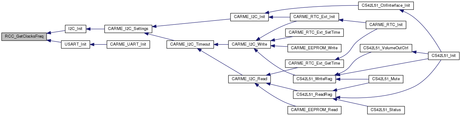
 Collaboration diagram for System AHB and APB busses clocks configuration functions:
 1.8.10