|
CARME-M4 BSP
V1.5
|
|
CARME-M4 BSP
V1.5
|
PWR driver modules. More...
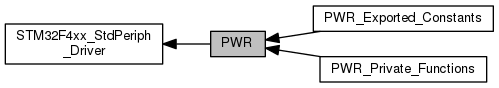
 Collaboration diagram for PWR:
Modules | |
| PWR_Exported_Constants | |
| PWR_Private_Functions | |
Functions | |
| void | PWR_DeInit (void) |
| Deinitializes the PWR peripheral registers to their default reset values. More... | |
| void | PWR_BackupAccessCmd (FunctionalState NewState) |
| Enables or disables access to the backup domain (RTC registers, RTC backup data registers and backup SRAM). More... | |
| void | PWR_PVDLevelConfig (uint32_t PWR_PVDLevel) |
| Configures the voltage threshold detected by the Power Voltage Detector(PVD). More... | |
| void | PWR_PVDCmd (FunctionalState NewState) |
| Enables or disables the Power Voltage Detector(PVD). More... | |
| void | PWR_WakeUpPinCmd (FunctionalState NewState) |
| Enables or disables the WakeUp Pin functionality. More... | |
| void | PWR_BackupRegulatorCmd (FunctionalState NewState) |
| Enables or disables the Backup Regulator. More... | |
| void | PWR_MainRegulatorModeConfig (uint32_t PWR_Regulator_Voltage) |
| Configures the main internal regulator output voltage. More... | |
| void | PWR_OverDriveCmd (FunctionalState NewState) |
| Enables or disables the Over-Drive. More... | |
| void | PWR_OverDriveSWCmd (FunctionalState NewState) |
| Enables or disables the Over-Drive switching. More... | |
| void | PWR_UnderDriveCmd (FunctionalState NewState) |
| Enables or disables the Under-Drive mode. More... | |
| void | PWR_FlashPowerDownCmd (FunctionalState NewState) |
| Enables or disables the Flash Power Down in STOP mode. More... | |
| void | PWR_EnterSTOPMode (uint32_t PWR_Regulator, uint8_t PWR_STOPEntry) |
| Enters STOP mode. More... | |
| void | PWR_EnterUnderDriveSTOPMode (uint32_t PWR_Regulator, uint8_t PWR_STOPEntry) |
| Enters in Under-Drive STOP mode. More... | |
| void | PWR_EnterSTANDBYMode (void) |
| Enters STANDBY mode. More... | |
| FlagStatus | PWR_GetFlagStatus (uint32_t PWR_FLAG) |
| Checks whether the specified PWR flag is set or not. More... | |
| void | PWR_ClearFlag (uint32_t PWR_FLAG) |
| Clears the PWR's pending flags. More... | |
PWR driver modules.
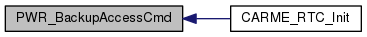
| void PWR_BackupAccessCmd | ( | FunctionalState | NewState | ) |
Enables or disables access to the backup domain (RTC registers, RTC backup data registers and backup SRAM).
| NewState | new state of the access to the backup domain. This parameter can be: ENABLE or DISABLE. |
| None |
Definition at line 149 of file stm32f4xx_pwr.c.
Here is the caller graph for this function:| void PWR_BackupRegulatorCmd | ( | FunctionalState | NewState | ) |
Enables or disables the Backup Regulator.
| NewState | new state of the Backup Regulator. This parameter can be: ENABLE or DISABLE. |
| None |
Definition at line 353 of file stm32f4xx_pwr.c.
| void PWR_ClearFlag | ( | uint32_t | PWR_FLAG | ) |
Clears the PWR's pending flags.
| PWR_FLAG | specifies the flag to clear. This parameter can be one of the following values:
|
| None |
Definition at line 848 of file stm32f4xx_pwr.c.
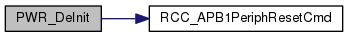
| void PWR_DeInit | ( | void | ) |
Deinitializes the PWR peripheral registers to their default reset values.
| None |
| None |
Definition at line 134 of file stm32f4xx_pwr.c.
Here is the call graph for this function:| void PWR_EnterSTANDBYMode | ( | void | ) |
Enters STANDBY mode.
| None |
| None |
Definition at line 757 of file stm32f4xx_pwr.c.
| void PWR_EnterSTOPMode | ( | uint32_t | PWR_Regulator, |
| uint8_t | PWR_STOPEntry | ||
| ) |
Enters STOP mode.
| PWR_Regulator | specifies the regulator state in STOP mode. This parameter can be one of the following values:
|
| PWR_STOPEntry | specifies if STOP mode in entered with WFI or WFE instruction. This parameter can be one of the following values:
|
| None |
Definition at line 645 of file stm32f4xx_pwr.c.
| void PWR_EnterUnderDriveSTOPMode | ( | uint32_t | PWR_Regulator, |
| uint8_t | PWR_STOPEntry | ||
| ) |
Enters in Under-Drive STOP mode.
| PWR_Regulator | specifies the regulator state in STOP mode. This parameter can be one of the following values:
|
| PWR_STOPEntry | specifies if STOP mode in entered with WFI or WFE instruction. This parameter can be one of the following values:
|
| None |
Definition at line 709 of file stm32f4xx_pwr.c.
| void PWR_FlashPowerDownCmd | ( | FunctionalState | NewState | ) |
Enables or disables the Flash Power Down in STOP mode.
| NewState | new state of the Flash power mode. This parameter can be: ENABLE or DISABLE. |
| None |
Definition at line 499 of file stm32f4xx_pwr.c.
| FlagStatus PWR_GetFlagStatus | ( | uint32_t | PWR_FLAG | ) |
Checks whether the specified PWR flag is set or not.
| PWR_FLAG | specifies the flag to check. This parameter can be one of the following values:
|
| The | new state of PWR_FLAG (SET or RESET). |
Definition at line 820 of file stm32f4xx_pwr.c.
| void PWR_MainRegulatorModeConfig | ( | uint32_t | PWR_Regulator_Voltage | ) |
Configures the main internal regulator output voltage.
| PWR_Regulator_Voltage | specifies the regulator output voltage to achieve a tradeoff between performance and power consumption when the device does not operate at the maximum frequency (refer to the datasheets for more details). This parameter can be one of the following values:
|
| None |
Definition at line 375 of file stm32f4xx_pwr.c.
| void PWR_OverDriveCmd | ( | FunctionalState | NewState | ) |
Enables or disables the Over-Drive.
| NewState | new state of the Over Drive mode. This parameter can be: ENABLE or DISABLE. |
| None |
Definition at line 410 of file stm32f4xx_pwr.c.
| void PWR_OverDriveSWCmd | ( | FunctionalState | NewState | ) |
Enables or disables the Over-Drive switching.
| NewState | new state of the Over Drive switching mode. This parameter can be: ENABLE or DISABLE. |
| None |
Definition at line 428 of file stm32f4xx_pwr.c.
| void PWR_PVDCmd | ( | FunctionalState | NewState | ) |
Enables or disables the Power Voltage Detector(PVD).
| NewState | new state of the PVD. This parameter can be: ENABLE or DISABLE. |
| None |
Definition at line 222 of file stm32f4xx_pwr.c.
| void PWR_PVDLevelConfig | ( | uint32_t | PWR_PVDLevel | ) |
Configures the voltage threshold detected by the Power Voltage Detector(PVD).
| PWR_PVDLevel | specifies the PVD detection level This parameter can be one of the following values:
|
| None |
Definition at line 197 of file stm32f4xx_pwr.c.
| void PWR_UnderDriveCmd | ( | FunctionalState | NewState | ) |
Enables or disables the Under-Drive mode.
| NewState | new state of the Under Drive mode. This parameter can be: ENABLE or DISABLE. |
| None |
Definition at line 455 of file stm32f4xx_pwr.c.
| void PWR_WakeUpPinCmd | ( | FunctionalState | NewState | ) |
Enables or disables the WakeUp Pin functionality.
| NewState | new state of the WakeUp Pin functionality. This parameter can be: ENABLE or DISABLE. |
| None |
Definition at line 256 of file stm32f4xx_pwr.c.
 1.8.10