|
CARME-M4 BSP
V1.5
|
|
CARME-M4 BSP
V1.5
|
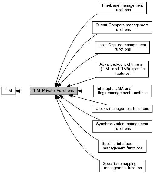
 Collaboration diagram for TIM_Private_Functions:
Modules | |
| TimeBase management functions | |
| TimeBase management functions. | |
| Output Compare management functions | |
| Output Compare management functions. | |
| Input Capture management functions | |
| Input Capture management functions. | |
| Advanced-control timers (TIM1 and TIM8) specific features | |
| Advanced-control timers (TIM1 and TIM8) specific features. | |
| Interrupts DMA and flags management functions | |
| Interrupts, DMA and flags management functions. | |
| Clocks management functions | |
| Clocks management functions. | |
| Synchronization management functions | |
| Synchronization management functions. | |
| Specific interface management functions | |
| Specific interface management functions. | |
| Specific remapping management function | |
| Specific remapping management function. | |
Functions | |
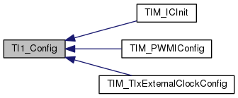
| static void | TI1_Config (TIM_TypeDef *TIMx, uint16_t TIM_ICPolarity, uint16_t TIM_ICSelection, uint16_t TIM_ICFilter) |
| Configure the TI1 as Input. More... | |
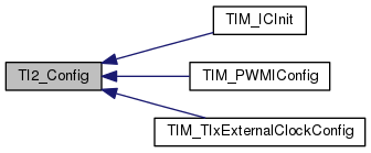
| static void | TI2_Config (TIM_TypeDef *TIMx, uint16_t TIM_ICPolarity, uint16_t TIM_ICSelection, uint16_t TIM_ICFilter) |
| Configure the TI2 as Input. More... | |
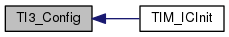
| static void | TI3_Config (TIM_TypeDef *TIMx, uint16_t TIM_ICPolarity, uint16_t TIM_ICSelection, uint16_t TIM_ICFilter) |
| Configure the TI3 as Input. More... | |
| static void | TI4_Config (TIM_TypeDef *TIMx, uint16_t TIM_ICPolarity, uint16_t TIM_ICSelection, uint16_t TIM_ICFilter) |
| Configure the TI4 as Input. More... | |
|
static |
Configure the TI1 as Input.
| TIMx | where x can be 1, 2, 3, 4, 5, 8, 9, 10, 11, 12, 13 or 14 to select the TIM peripheral. |
| TIM_ICPolarity | : The Input Polarity. This parameter can be one of the following values:
|
| TIM_ICSelection | specifies the input to be used. This parameter can be one of the following values:
|
| TIM_ICFilter | Specifies the Input Capture Filter. This parameter must be a value between 0x00 and 0x0F. |
| None |
Definition at line 3204 of file stm32f4xx_tim.c.
Here is the caller graph for this function:
|
static |
Configure the TI2 as Input.
| TIMx | where x can be 1, 2, 3, 4, 5, 8, 9 or 12 to select the TIM peripheral. |
| TIM_ICPolarity | : The Input Polarity. This parameter can be one of the following values:
|
| TIM_ICSelection | specifies the input to be used. This parameter can be one of the following values:
|
| TIM_ICFilter | Specifies the Input Capture Filter. This parameter must be a value between 0x00 and 0x0F. |
| None |
Definition at line 3245 of file stm32f4xx_tim.c.
Here is the caller graph for this function:
|
static |
Configure the TI3 as Input.
| TIMx | where x can be 1, 2, 3, 4, 5 or 8 to select the TIM peripheral. |
| TIM_ICPolarity | : The Input Polarity. This parameter can be one of the following values:
|
| TIM_ICSelection | specifies the input to be used. This parameter can be one of the following values:
|
| TIM_ICFilter | Specifies the Input Capture Filter. This parameter must be a value between 0x00 and 0x0F. |
| None |
Definition at line 3287 of file stm32f4xx_tim.c.
Here is the caller graph for this function:
|
static |
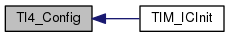
Configure the TI4 as Input.
| TIMx | where x can be 1, 2, 3, 4, 5 or 8 to select the TIM peripheral. |
| TIM_ICPolarity | : The Input Polarity. This parameter can be one of the following values:
|
| TIM_ICSelection | specifies the input to be used. This parameter can be one of the following values:
|
| TIM_ICFilter | Specifies the Input Capture Filter. This parameter must be a value between 0x00 and 0x0F. |
| None |
Definition at line 3328 of file stm32f4xx_tim.c.
Here is the caller graph for this function: 1.8.10